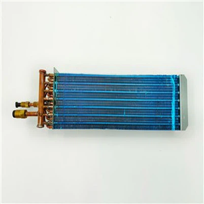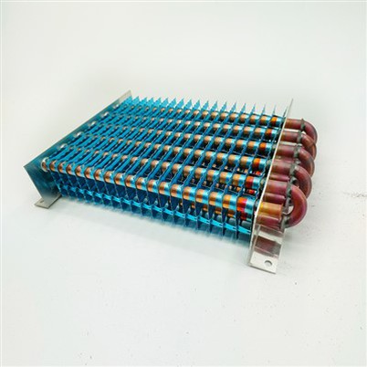
Air Conditioning Finned Heat Exchanger 8 Design Parameters
Leave a message
Heat exchanger temperature parameters: the evaporation temperature is usually 3-8 ° C, and the condensation temperature is usually 45-54 ° C (this is the temperature value calculated by the design of the comfort air conditioner, and the nominal cooling capacity of the compressor is also tested in accordance with this). The inlet and outlet air temperature difference is usually 8-10 ° C, and the temperature difference of the evaporator will be smaller in the low-temperature device. The temperature difference between evaporation temperature, condensation temperature and outlet air temperature is usually about 10℃.
The superheat in the evaporator is usually 5-10 ° C (the superheat is different from the suction temperature, and there is a great difference in the splitter or low-temperature device), and the supercooling in the condenser is usually 5-8 ° C.
The head-on wind speed of the evaporator is usually 1.5-3m/s, the condenser is 2-3m/s, the wind speed on the narrowest side should not exceed 6m/s, and the wind speed of 2.5m/s is used in most cases.
Pipe diameter and thickness: Usually 9.52mm, 7.94mm, 7mm and 5mm internally threaded copper pipe or light pipe, smaller pipe diameter can improve the heat transfer efficiency.
Row spacing x row spacing: Usually in the form of equilateral triangle rows, such as 25.4x22mm, 25x21.65mm, etc. You can also use 25.4x19.5mm, 21x13.6mm and so on.
Fins: Usually select the thickness of 0.095-0.3mm, spacing of 1.1-2.5mm fins. Because there is condensate in the evaporator, the spacing should be larger; Because the condenser is a dry heat exchange, it can be selected to be smaller. Taking into account the frost problem, the evaporator of the refrigeration unit is usually between 3-6mm. For condensers in evaporators or heat pump systems, hydrophilic aluminum plates are usually used. Some also use plain tablets and spray paint to prevent rust. The shape of the fin is mainly a flat piece, a corrugated piece, a slit piece and a corrugated slit piece that combines the two.
Pipeline structure: The evaporator is usually composed of 2-6 rows, and the condenser is composed of 1-6 rows. Too many rows will cause the heat transfer effect of the rear row to be poor. If more rows must be used due to structural limitations, the head-on wind speed needs to be appropriately increased to ensure the air volume of the rear row. Each loop usually does not exceed 12-18m, the evaporator takes the limit value, the condenser takes the upper limit value. Of course, this also takes into account the refrigerant mass flow rate. Too short a pipe can not adequately transfer heat, too long a pipe will lead to a large pressure drop, different pipe diameter resistance is also different. The pressure drop of the evaporator should not exceed 5% of the evaporation pressure, and the condenser should not exceed 2% of the condensing pressure, otherwise it will reduce the efficiency of the unit. Usually after the fin parameters are selected, the outer area per unit length can be calculated, and then the total length required can be calculated. For evaporators, some aspect ratios may be larger due to limitations in height or considerations when choosing a fan. For the condenser, due to the various structural forms, such as U shape, V shape, L shape, etc., it is only necessary to increase the windward area as much as possible.
Flow path design: The general point of view is that the evaporator is usually down in and out (refrigerant evaporates into a gas to flow upward, avoiding accumulation in the tube affecting heat transfer), and then back in and forward out (forming a countercurrent with the inlet air). The condenser is usually upward and downward, and backward and forward (so that the condensed liquid can use gravity to flow out of the condenser as soon as possible). However, these are only the views of heat transfer enhancement on one side of heat transfer, in fact, the heat transfer process of air conditioning heat exchanger is a complex process, and the factors affecting the heat transfer efficiency are also many.
Here are some guidelines for influencing factors:
a. The inlet and outlet should be as far apart as possible to avoid reheating.
b. Do not only enter from one side and exit from the other side, so that both sides flow through to avoid overheating or cooling on one side, resulting in uneven heat transfer and reducing heat transfer efficiency.
c. With the increase of the dryness of the refrigerant in the pipeline, the heat transfer efficiency continues to improve, so the heat transfer capacity of the back section of the flow path is higher than that of the front section.
The following two ideas can be considered when designing a loop:
a. For the evaporator, with the increase of refrigerant gas, the pressure drop and heat transfer coefficient will also increase, so less inlet shunt can be designed at the inlet of the evaporator, and then the shunt can be increased at the back in order to reduce the gas to reduce the pressure drop. Plan D mentioned above is designed in this way. For the condenser, on the contrary, more inlet shunt is designed at the beginning, and the condensed liquid can be gathered to reduce the shunt, so as to increase the flow rate, strengthen the heat transfer and increase the degree of supercooling, so this part is also called the supercooling pipe. Now some condensers have adopted such a design. Since the condenser is usually up and down, the collecting tube is usually located at the bottom, and there is information that such a reinforced design can also help the heat pump better defrost.
b. The heat transfer effect of the windward side and the leeward side of the heat exchanger is quite different. For example, when the wind speed is 0.5m/s, the heat transfer on the windward side accounts for 96.3% of the total heat transfer, and when the wind speed is 3.0m/s, the heat transfer on the windward side accounts for 69.2% of the total heat transfer. This is mainly due to the change in heat transfer temperature difference. On the lee side, the temperature difference becomes smaller, resulting in a poorer heat transfer effect. Some companies have designed condensers with the following structures, of which #5 works best. Therefore, it is necessary to consider how to improve the heat transfer efficiency of the leeward side pipeline, such as increasing the wind speed and reducing the windward side and heat transfer efficiency, that is, reducing the air outlet temperature of the windward side.